")
")
How can the frequency response of a microphone be measured?
A microphone converts sound pressure into an electrical voltage.
How can you measure the transmission behavior for different frequencies?
The best solution: an absorber chamber (anechoic chamber)
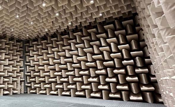
Free field conditions for sound mean, free propagation as a spherical wave. These theoretical conditions can only be achieved in practice with limitations. Any object near the sound source or microphone causes the sound to be reflected. These reflections lead to undesirable reductions or increases in the frequency response. Efforts are made to cover all walls and other reflective surfaces with absorbent materials. For higher frequencies (>300Hz) this works quite well with porous materials (foam, insulating wool). However, at low frequencies this becomes much more difficult.
Absorber chambers must be as large as possible in order to have a large distance from the walls. Overall, the effort required for efficient absorber chambers is enormous. Therefore, only a few laboratories have such rooms.
However, if such space is available, the substitution method is used. A sound source is measured with a reference microphone. The test microphone is then measured at the identical position. The difference to the reference microphone results in the desired frequency response of the test microphone. Since these are almost free field conditions, the position of the microphones is not that critical. The only thing that matters is the distance to the sound source. However, in real rooms the position should be repeated with millimeter precision.
An absorber chamber is indispensable
The frequency response of a sound level meter does not only depend on the microphone. Diffraction effects and reflections from other parts of the sound level meter can significantly change the frequency response. Therefore, some devices such as the NTI XL2 in the pattern-tested version have to be operated with a detached microphone.
Another example is incorrectly sized pressure compensation openings in the microphone capsule.
Such effects can only be determined under free field conditions, as only then do all components interact with the sound field.
Electrostatic actuator
A free-field measurement is far too complex for quality assurance during production. The same applies to the ongoing monitoring of measuring equipment in larger companies. A condenser microphone can not only be excited by sound but also by an electric field. You unscrew the protective grid and replace it with an electrostatic actuator. The purely electrical transmission function between the actuator and the output of the microphone is measured. The relationship between the free field transfer function and the actuator transfer function must be measured once for each type of microphone. The free-field frequency response can then be calculated by making a correction. This works as long as the basic design of the microphone is not changed. This measurement is quick, regardless of the room or other sources of acoustic interference. This measuring method only works with condenser microphone designs defined in accordance with DIN/IEC61094. Microphones with permanently installed electret microphones, such as Behringer ECM8000 or UMIK-1, cannot be measured in this way.
Reciprocity procedure
Microphone calibration using the reciprocity method is used to determine the transmission factor of laboratory-standard microphones with the lowest possible measurement uncertainty. The process is internationally standardized according to DIN/IEC 61094-2. This calibration method is based on the fact that condenser microphones are reciprocal sound transducers. Reciprocal sound transducers can be used both as sound receivers and as sound transmitters. A condenser microphone also works as a speaker. This effect is also used with electrostatic headphones. The crucial thing is that the transmission properties can be converted in both directions. In the reciprocity method, 2 out of 3 microphones are acoustically coupled together, with one microphone acting as a sound transmitter and one microphone acting as a sound receiver. This procedure achieves the highest accuracy and is used in practice by special calibration laboratories and research institutions.
Precision sound pressure chamber
A defined sound pressure field can be much easier created than a free field. A small loudspeaker serves as a sound source and creates a pressure field in the smallest possible volume. Two microphones - acoustically coupled - are installed in this volume. A reference microphone and the microphone to be tested. Both microphones are exposed to acoustic conditions that are as identical as possible. It is therefore a direct comparison method. The frequency response of the speaker is irrelevant. The enormous advantage of this method is that, similar to the method with electrostatic actuator, it is independent of the room and other sources of acoustic interference. The microphones do not have to be laboriously positioned in the room as with the free field method. In principle, all types of microphones can be measured as long as they fit mechanically into the coupler and are closed at the back. The frequency range extends from approx. 30Hz to 16kHz. Higher frequencies in particular are a challenge for such measurement methods. Conversely, lower frequencies, which are hardly measurable in a normal room, can be measured very reproducibly and precisely. In principle, only microphones of similar design can be compared, otherwise the sound field in the coupler is no longer symmetrical. Furthermore, only microphones with identical equalization should be compared.
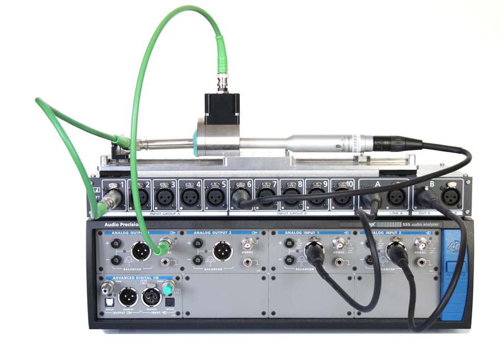
The picture above shows a complete acoustic measuring station
- APX555 audio analyzer from Audio Precision. This device also generates the test signals.
- Precision pressure chamber SQ4.2 vpn Spectra. On the left is the reference microphone, on the right is the test microphone. The loudspeaker is in the middle between the two microphones.
Kundt's pipe
The Kundt tube consists of a hollow cylinder. A defined sound field is generated in this cavity. This setup is mainly used to measure the absorption properties of materials. At one end there is a loudspeaker as a sound source. At the other end is the material sample. Microphones are inserted at various positions to measure the sound field. Microphones can be compared by exchanging the microphones, all other things remain equal.
Direct measurements in a normal room
It is very difficult to measure the transfer function of a microphone in a normal room. The effects of reflections overlay everything. Especially at higher frequencies (>300Hz) you can efficiently cover a room with absorbers. Here you can achieve almost free-field conditions with reasonable effort. You can also help yourself by measuring in the near field of a loudspeaker and filtering out reflections over time through the evaluation. A wave front also takes some time to reach the first wall starting from the speaker, then through the microphone. Therefore, only the first wave front is evaluated. But this only works at higher frequencies. The positioning of the microphones is always problematic because the sound field is extremely location-dependent. It is initially obvious to measure the two microphones at the same time. However, unwanted reflections occur between the microphones, which can significantly distort the measurement result.
In general, it is unfavorable to use extremely narrow-band signals, such as individual frequencies with a sine wave signal. Room resonances are particularly noticeable here. It is easier to use narrow-band noise (e.g. in third-octave bands). This means that a certain averaging takes place in the frequency range.
Combined procedures
Pressure chamber processes are well suited for lower frequencies. The design effort for a measuring box is very low. Conversely, higher frequencies can be measured reasonably sensibly in normal rooms. The idea is to first measure lower frequencies in the pressure field in a small measuring box and in the second step under quasi-free field conditions in a room that is only roughly acoustically treated. The different frequency ranges are combined in the evaluation. This process is occasionally found in the DIY sector. In the professional sector, a precision pressure chamber is used, which can be used reproducibly up to 16 kHz and is much more economical in series measurements. In particular, the time required is significantly less.
