")
")
Lab Measurements with the Audio Analyzer APX555 from Audio Precision
Since we own in our Lab the flagship Audio Analyzer APX555 from Audio Precision, we publish some measurement results from commercial devices.
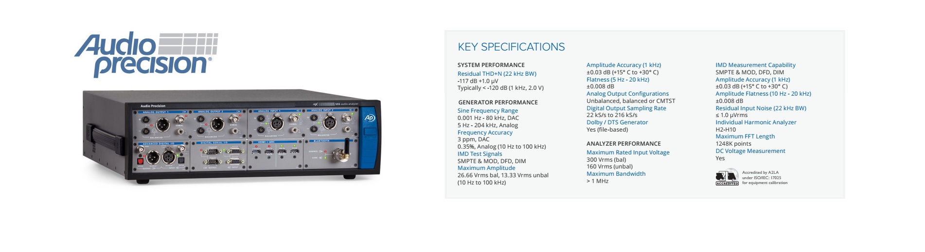
Please note, that we offer measurements from your devices in our LAB. You will get world leading measurement equipment plus our experienced engineering. The results from an audio analyzer APX555 from Audio Precision are worldwide recognized as a reference. We can do small series batch testing as well. Please do not hesitate to contact us.
Audio transformers: general information
Transformers are often used in audio technology to electrically isolate a signal path or to adjust the impedances. Input and output are coupled via a magnetic field. The input signal creates a magnetic field in the input winding (primary winding). This magnetic field in turn induces a voltage in the secondary winding. DC voltage is blocked. The turns ratio between the primary and secondary winding results in a transfer factor. As the voltage on the secondary winding increases, the output impedance also increases. As a passive component, a transformer cannot generate any power.
High levels and lower frequencies are a challenge for audio transformers because the magnetic transmission becomes non-linear. This creates distortions that manifest themselves as harmonics or intermodulation products.
There are small signal transformers that can be found in preamplifiers. However, power transformers can be found in tube power amplifiers
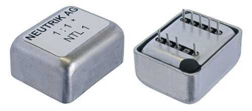
Small signal transformer Neutrik NTL-1
The transformer Neutrik NTL-1 is a small signal transformer with a turns ratio of 1:1. The impedance is 600Ohm. The transformer is completely shielded by a metal housing.
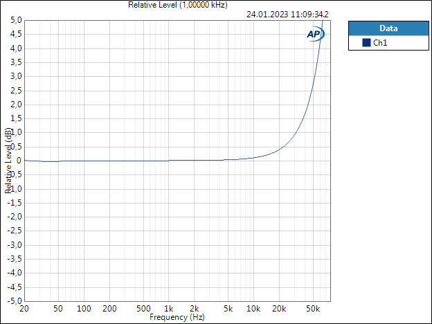
Frequency response of the Neutrik NTL-1
First, let's look at the frequency response. This is very linear across the entire audio range. Input level is 200mV RMS,
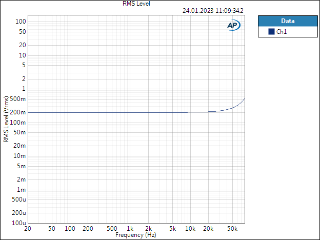
And the same measurement logarithmically, normalized to 0dB at 1kHz and enlarged
Linear usable area of the Neutrik NTL-1
Audio transformers are sensitive to high signal levels and low frequencies. THD+N increases with higher input level once we reached the minimum THD+N. The transfomer gets saturated and starts with clipping.
Input frequency is 1kHz.
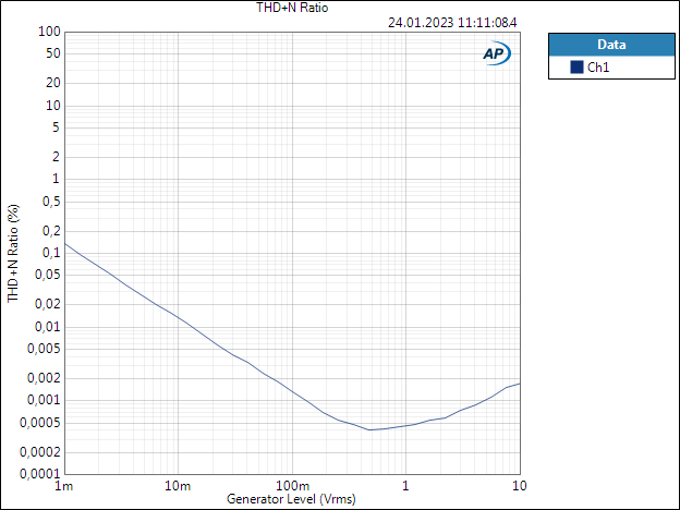
The range 1mV to 20mV is determined by the inherent noise of the APX555. However, above 20mV the non-linear effects of the transformer increase.
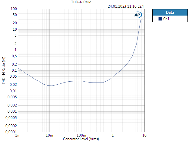
At 40Hz and the same level it looks significantly different. The distortions increase significantly,
Distortion components at lower frequencies
Audio transformers generally have non-linear effects at lower frequencies, which lead to distortions.
Input level is 50mV RMS
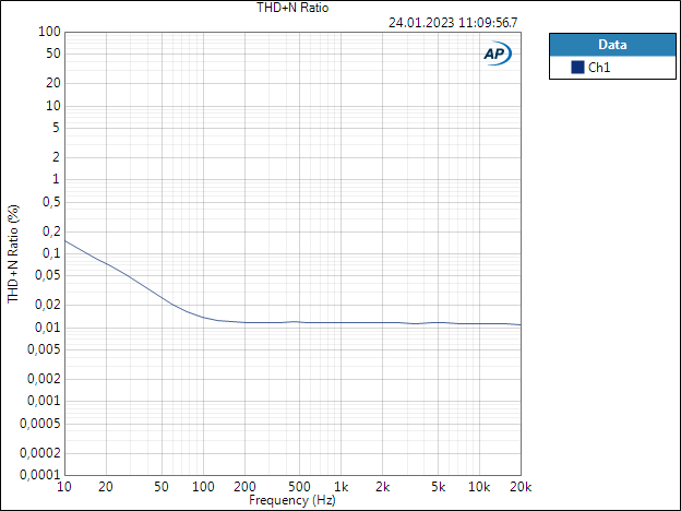
The following graphic shows the pure distortion (THD) instead of THD+N
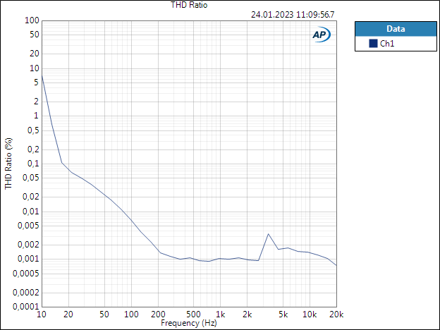
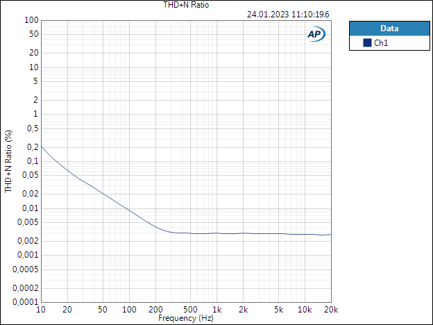
THD+N at an input level of 200mV.
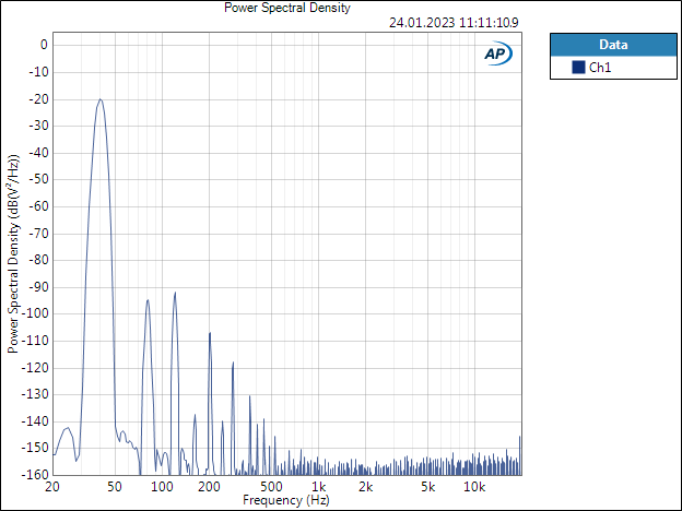
FFT spectrum for distortion analysis
Input level is 200mV RMS at 1kHz. The best possible area.
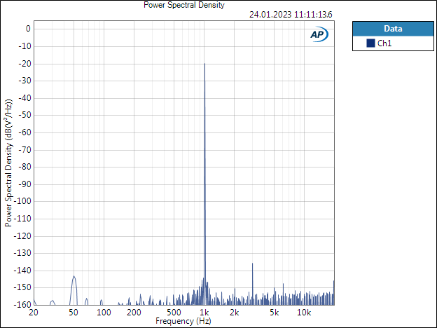
The distortions are extremely low.
At 40Hz and also 200mV RMS there are clear distortions